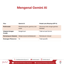
To create an Entity Relationship Diagram (ERD) easily, you can follow these four practical steps that are simple to understand and apply.
An Entity Relationship Diagram (ERD) is a visual representation used to design a database and illustrate the relationships between entities, objects, and their attributes in a detailed manner. ERDs are widely used in database design and software development to help developers understand data structures before implementation.
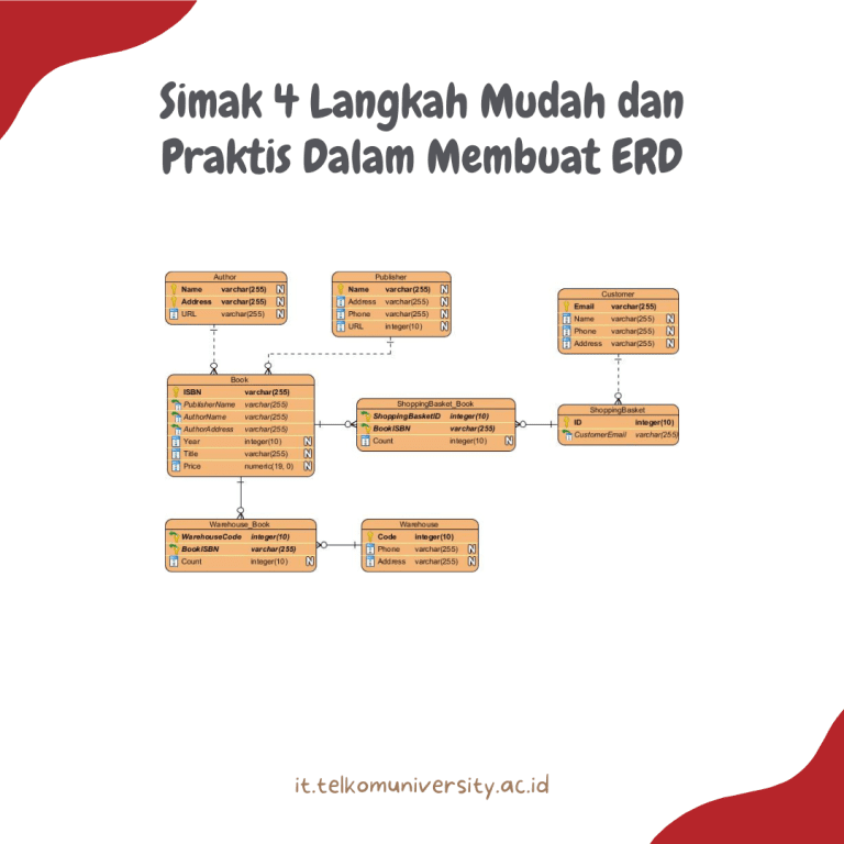
4 Easy Steps to Create an Entity Relationship Diagram (ERD)
An Entity Relationship Diagram (ERD) is one of the most important tools in database design. It is used to represent data structures, relationships between entities, and the attributes associated with each entity within a system. By using an ERD, developers can better understand how data flows and interacts before building the actual database.
For beginners, creating an ERD is not as difficult as it may seem. You simply need to follow a few fundamental steps systematically. Here are four easy steps you can follow.
1. Identify the Entities to Be Used
The first step in creating an ERD is identifying all the entities that will be included in the system or database.
An entity is a primary object whose data will be stored in the database, such as Student, Lecturer, Product, Customer, or Transaction.
In an ERD, entities are typically represented by rectangles. The name of the entity should be written clearly and concisely inside the rectangle.
For example, in an academic information system, possible entities may include:
- Student
- Lecturer
- Course
- Class
- Grade
This identification stage is crucial because it forms the foundation of the entire database structure.
2. Identify and Define Relationships Between Entities
After identifying the entities, the next step is to determine the relationships between them.
A relationship explains how one entity is connected to another within the system.
In an ERD, relationships are usually represented by lines connecting entities, while a diamond-shaped symbol may be used to describe the type of relationship.
You also need to determine the cardinality of each relationship, which defines how entities interact with one another:
One-to-One (1:1)
One entity is related to only one instance of another entity.
One-to-Many (1)
One entity can be related to multiple instances of another entity.
Many-to-Many (M)
Multiple instances of one entity can be related to multiple instances of another entity.
For example, in an academic system:
- One Lecturer can teach many Courses (1).
- One Student can enroll in many Courses (M).
Defining relationships clearly helps establish how data will be connected within the database.
3. Add Attributes to Each Entity
Once entities and relationships have been defined, the next step is adding attributes to each entity.
An attribute is a piece of information or a characteristic associated with an entity.
In an ERD, attributes are typically represented by oval shapes connected to their corresponding entity.
For example, the Student entity may contain the following attributes:
- Student ID
- Name
- Study Program
- Date of Birth
- Address
One of the most important attributes is the Primary Key, which uniquely identifies each record within an entity.
In ERDs, primary key attributes are usually underlined to distinguish them from other attributes.
4. Complete and Evaluate the Diagram
The final step is to complete and review the ERD you have created.
At this stage, ensure that all components accurately reflect the requirements of the system being developed.
Some important aspects to verify include:
- Have all entities been correctly identified?
- Are the relationships between entities accurate?
- Are all necessary attributes included?
- Are the symbols and diagram elements properly placed?
This evaluation process is essential to prevent errors during database implementation. A clear and comprehensive ERD makes database development significantly easier and more organized.
Conclusion
Creating an Entity Relationship Diagram (ERD) is an essential step in designing a structured and efficient database. The process can be completed through four main stages: identifying entities, defining relationships between entities, adding attributes, and reviewing and refining the diagram.
By following these steps systematically, developers can create a clear database structure that minimizes errors and improves the overall system development process. A well-designed ERD serves as a strong foundation for building reliable and scalable database systems.
References
Draw.io. Entity Relationship Diagram (ERD) Guide.
https://drawio-app.com/erd/
Codepolitan. What Is an ERD (Entity Relationship Diagram): Definition, Examples, and Implementation.
https://codepolitan.com/blog/apa-itu-erd-entity-relationship-diagram-pengertian-contoh-dan-implementasinya
Telkom University Business Systems Engineering. Entity Relationship Diagram (ERD) in Software Engineering.
https://bse.telkomuniversity.ac.id/entity-relationship-diagram-erd-dalam-rekayasa-perangkat-lunak/
Telkom University Open Library Publications. Research on ERD and Database Design.
https://openlibrarypublications.telkomuniversity.ac.id/index.php/engineering/article/view/20513/19826